The enquiries we get on this always arrive in the same shape: "we have the 3D models of the machine, how long to put them in a headset?".
The honest answer is that the 3D models you have do not exist, in the sense that matters. A CAD file does not contain meshes: it contains mathematical surfaces. And the target you want them running on has about 13 milliseconds to draw two images, one per eye, every time somebody moves their head. Between those two facts sits a pipeline, and that is where the work is.
The constraint that governs everything
A Quest 3 runs at 72 Hz by default and goes up to 90 or 120. At 72 Hz you have 13.9 ms per frame; at 90 Hz you have 11.1. In that time the mobile chipset has to draw the scene twice, with two slightly different projection matrices.
Miss the budget and the experience does not become "less smooth": the compositor starts reprojecting old frames, the world detaches from head movement, and the person wearing the headset feels ill. That is not an aesthetic problem, it is people taking the headset off after ninety seconds.
Everything below exists to stay inside that budget.
What actually comes out of a CAD system
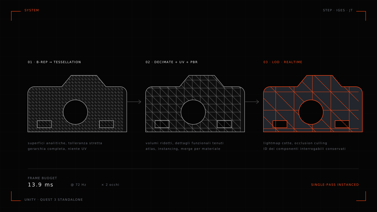
A native mechanical assembly (SolidWorks, Inventor, NX) is B-Rep: geometry described by analytic surfaces and topology, not triangles. To get it into a realtime engine it has to be tessellated, approximating those surfaces with a mesh, and the tessellation tolerance decides how many triangles come out. Tight enough to render a fillet properly, it produces numbers counted in millions for a single subassembly.
Then come the problems nobody mentions.
The hierarchy. An industrial assembly has thousands of nodes, including every single screw, washer and bracket. In a realtime engine each separate node is a potential draw call.
Normals and faces. Exports through STEP or IGES arrive with inconsistent normals and flipped faces, which on screen means black surfaces or wrong shading along edges.
No UVs. CAD does not need them, PBR rendering does. They have to be generated.
No materials. In CAD, "stainless steel" is a label with a density, not a set of albedo, metallic, roughness and normal maps.
Internal geometry. A design model contains everything inside the machine, including parts nobody will ever see. Those are triangles you pay for on every frame.
The first step of the pipeline is not "optimise": it is deciding what exists in the application.
Reducing without lying
Automatic decimation works well on large surfaces and badly wherever shape carries information. On a housing it is fine; on a thread, a cutting profile, or an area where the customer wants to understand a fit, it produces results an engineer recognises as fake. And the customer looking at it is an engineer.
So you work at two speeds: aggressive decimation on the parts that make up volume, selective replacement or remodelling on the details that carry meaning. Screws and fasteners are usually swapped for low-count versions and instanced, because they are thousands of copies of the same object.
On top of that you build LODs: decreasing-density versions the engine swaps with distance. On a twenty-metre line, where the visitor stands near one machine at a time, it is the single optimisation with the best cost-benefit ratio.
The real enemy is draw calls
On desktop hardware you can be generous with object counts; on a mobile chipset you cannot. The cost is not only in triangles, it is in how many times the CPU tells the GPU to draw something.
The countermeasures are well known and have to be applied together: merge static meshes that share a material, cut the number of distinct materials by building texture atlases, use GPU instancing for anything repeated, and enable single-pass instanced stereo rendering, which draws both eyes in one pass instead of two.
Then there is occlusion culling, which works beautifully in a factory: inside a shed, most of the scene is hidden behind the nearest machines.
Light gets baked first
Realtime lighting with dynamic shadows across the whole scene is out of budget on standalone. What you do instead is bake static lighting into lightmaps, keep dynamic only the few lights that genuinely change, and use reflection probes for metal surfaces, which on industrial plant is more or less everything.
Baking is also the moment you discover that the automatically generated UVs overlap, and that part of the preparation work has to be redone. It always happens.
Keeping the link to the data
This is what separates a useful application from a demo, and it is the first thing to break when optimisation is done with an axe.
Every component that has to be queryable — point at it, get its data sheet, its part number, its spares — must keep a stable identifier that survives decimation, merging and hierarchy reorganisation. Merge twenty meshes into one to save draw calls and you have lost the ability to select them individually.
The rule we use is simple: decide first which components are interactive, keep those as separate entities with their IDs, and merge everything else freely. Doing it afterwards means redoing the optimisation.
In the project for Emmepi, where pointing at a component opens its data sheet, the data comes from their own technical material and is attached to the nodes we deliberately kept alive. The exploded views and the material-flow animations along the line live on the same hierarchy.
One thing worth being pedantic about: an exploded view has to make mechanical sense. If parts move apart in directions that do not match how the machine is actually disassembled, the people who assemble it for a living notice, and stop trusting the rest.
Two targets, two builds
Sales teams have two incompatible contexts, which is why in projects like the one for Surteco we built two applications rather than one.
Tethered (headset connected to a PC) is for showrooms and trade shows: the GPU is real, the polygon budget is another planet, and you can keep advanced lighting and large catalogues loaded locally.
Standalone is what the rep packs in a suitcase: no cable, no PC, switch on and go. In exchange, it dictates every rule above.
Trying to serve both with a single build means, in practice, shipping the standalone version to people who had the hardware for something better.
What stays out
For the sake of honesty, the list of things this pipeline does not do.
It is not a physics simulation: the animations are kinematics signed off by people who know the machine, not a solver. It does not check tolerances or interferences; CAE tools exist for that and that is where it belongs. And it does not replace commissioning: it is there to make things understood, decided and taught, which is already three jobs.
If you have an assembly weighing a few gigabytes and a trade show in two months, the technical question to start from is not which engine to use, but which components have to stay queryable. Almost everything else follows from that answer.
We build XR applications and 3D software starting from engineering data: what System does, the Explore framework we use for interactions, or get in touch.